


Please Leave Us A Message
Privacy statement: Your privacy is very important to Us. Our company promises not to disclose your personal information to any external company with out your explicit permission.
Yangzhou Tongyang Chemical Equipment Co., Ltd.
sunjiawei@yzcheequipt.com
86--18556139427

 May 20, 2022
Yang Shenglin Wei Xiaoping
(China Petroleum Engineering Construction Corporation, Beijing 100011)
【Abstract】The chemical composition analysis and mechanical properties of the tubes leaking from the U-Tube Heat Exchanger were carried out. The microstructure and fracture analysis of the cracks were carried out by means of optical and scanning electron microscopy. The reason for the cracking of the pipe at the pipe joint is the stress corrosion (SCC) caused by the continuous polysulfuric acid.
Key words: U-tube Heat Exchanger, austenitic stainless steel, polysulfate, stress corrosion
A refinery has a kerosene hydrogenation unit with a position of E-001B. The U-tube heat exchanger has frequent leaks at the pipe head. It occurs twice in the shortest 7 days, which seriously affects the long-term operation of the device. In this paper, the causes of the cracking of the heat exchanger tube are analyzed and the reason for the cracking of the heat exchange tube is obtained.
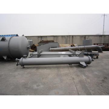
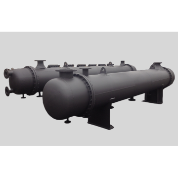
1 U-tube heat exchanger basic parameters
Table 1 E-001B reaction distillate / low oil heat exchanger operating conditions
2 Macroscopic inspection of the failed heat exchanger The connection diagram of the pipe and the tube sheet and the crack location are shown in Fig. 1. According to the test results of the process medium, the H2S concentration in the low oil is about 300ppm-500ppm, and the liquid water is 60ppm-70ppm under normal production conditions (the liquid water content sometimes exceeds the ppm level due to misuse); The concentration of H2S in the distillate is about 18000ppm-20000ppm, wherein the gas-oil ratio (hydrogen: straight-run kerosene) is 400:1. In addition, the reaction distillate also contains impurities such as HCl, NH4Cl, N2, etc. The ion content is affected by the dechlorination effect of the electric desalting of the atmospheric and vacuum distillation unit.
3 Inspection and inspection of failed heat exchanger tubes
3.1 Microscopic examination of the connection form of tube and tube of heat exchanger
In order to determine the location of the leakage of E-001B, provide basic data for the next analysis and study, and perform coloring inspection on the part of the E-001B tube plate where no repair welding is performed to determine whether the tube and the tube plate are welded or not. The direction of the crack. The test results show that on the pipe protruding from the tube plate of 1.5 mm, cracks are generated along the axis of the pipe and spread into the pipe, and there are a large number of corrosion pits on the pipe plate and the pipe (this is a pit erosion caused by chloride ions). ).
3.2 chemical composition analysis
Take a pipe of about 250 mm long which leaks in the E-001B heat exchanger tube bundle as a sample for chemical composition analysis. The results are shown in Table 2. The analysis results show that the pipe material fully meets the requirements of the chemical composition of 0Cr18Ni10Ti stainless steel in GB13296-2007 "Stainless Steel Seamless Steel Tube for Boiler and Heat Exchanger".
3.3 Normal temperature tensile test
In order to analyze whether the 0Cr18Ni10Ti stainless steel heat exchange tube has deteriorated due to material deterioration during service, three tubes with a length of 250mm are cut in the non-cracked tube bundle for tensile performance test. The test is carried out according to GB228-1998 standard. See Table 3.
The tensile test results show that the tensile properties of the pipe meet the tensile performance requirements of 0Cr18Ni10Ti stainless steel pipe in GB13296-200 "7 stainless steel seamless steel tubes for boilers and Heat Exchangers".
3.4 hardness test
The tube was cut and flattened along the longitudinal section of the tube for hardness testing. The results are shown in Table 4. The hardness test results show that except for the hardness of the middle part, the hardness of the other parts basically meets the relevant standards.
3.5 metallographic examination
Take the metallographic test of the pipe without the cracked pipe section and the nozzle sample with the crack (cracking tip) at the pipe head, and observe the metallographic phase of the pipe without cracking in the longitudinal direction, and observe the longitudinal section of the pipe containing the crack. The cross section is cut, and the sample is mechanically polished and chemically etched after sampling. The metallographic structure and crack morphology of the pipe and weld are shown in Figure 2.
Fig. 2(a) shows the metallographic structure of the un-cracked pipe section. It can be seen that the metallographic structure is a uniform single-phase austenite with twin crystals, the metallographic structure is normal, and the small black dots in the figure are precipitated carbides; (b) is the metallographic structure of the weld metal; Figure 2 (c) is the metallographic diagram at the nozzle, which is a typical intergranular corrosion crack: the crack is in the form of crystal growth, the crack depth is about 2-3 The grain thickness, and the cracks along the crystal crack, have been isolated from each other. From the crack morphology analysis shown above, it can be seen that the stainless steel tube bundle may be corroded by a large amount of sulfides and chlorides during service, and the crack morphology exhibits typical stress corrosion (continuous polysulfate stress corrosion and chloride stress corrosion) cracking. feature.
3.6 fracture energy spectrum analysis
A sample containing cracks was taken from the welded joint between the pipe and the tube sheet, and the crack was opened to analyze the energy spectrum of the fracture corrosion product. The results of the fracture energy spectrum analysis are shown in Table 5. It can be seen that a large amount of corrosion products on the fracture are basically oxides and sulfides, and contain a certain amount of chloride. It can be concluded that the cause of failure at the E-001B tube head is most likely related to sulfides and chlorides.
3.7 fracture scanning electron microscopy analysis
Figure 3 is a scanning electron microscope morphology of the crack section of the E-001B heat exchanger tube crack. It can be seen from the figure that there is a secondary crack on the fracture, and the fracture has a cleavage morphology, which has the characteristics of a river-like pattern and a muddy pattern, which is a common fracture morphology of stress corrosion.
4 Analysis of the causes of continuous polysulfate stress corrosion
In the literature [1], Li Zhiqiang studied the crack morphology of continuous polysulfate stress corrosion as intergranular cracks through a large number of engineering examples. Combined with the research results of this literature, the above analysis can be used to obtain the failure of the heat exchanger tube. The reason is that even polysulfate stress corrosion.
4.1 With the formation conditions of poly-sulfuric acid, if it is not protected or improperly protected, air will enter the Hydrogenation Reactor or E-001B. The air entering the Reactor during driving will follow the circulation of the hydrogen compressor. Turn on, the sulfide which flows out of the reactor with the gas circulation, and the effluent below the dew point, so that the surface of E-001B may produce polysulfuric acid; in addition, each time a leak occurs, the E-001B leaking part must be blocked first. The temperature of E-001B is lowered to normal temperature, and the hydrogenation workshop does not take any protective measures against the heat exchange tube and the air, so that oxygen is inevitably brought into direct contact with the heat exchange tube, resulting in a continuous formation from the surface. sulfuric acid. 4.2 The material sensitive to polysulfate is 0Cr18Ni10Ti austenitic stainless steel is very sensitive to Cl-, H2S, SO2 stress corrosion (not to be repeated here). It should be noted that, in general, if the carbon content in the stainless steel is less than 0.03%, the intergranular corrosion will be effectively prevented, but the chemical composition analysis of the E-001B tube bundle shows that the carbon content is about 0.043%, so such a content The amount of carbon is not sufficient to effectively prevent intergranular corrosion [2].
4.3 Stress conditions
At the nozzle, welding residual stress due to welding is also present, and even if the stress-relieving heat treatment is performed during the manufacturing process of the apparatus, the welding residual stress cannot be completely eliminated. In particular, after the first leak of E-001B, the nozzle has been repaired over a large area, and after the welding is completed, no heat treatment for eliminating the residual stress of the weld is performed (the heat treatment condition is not possible at the site), so It is certain that welding residual stress exists at the pipe head, and its direction is arbitrary, so residual stress along the circumferential direction of the pipe cannot be excluded, which is also one of the mechanical factors causing SCC at the nozzle. After the above three conditions are met, stress corrosion caused by continuous polysulfuric acid gas is generated at the tube head of the heat exchanger.
5 Conclusion
(1) During the maintenance of E-001B, a large amount of air entered the E-001B heat exchange tube due to improper maintenance. In the "cold state" and H2S+H2O conditions [2], polythionic acid was formed.
(2) While the tube is corroded by chloride ions (pitting), stress corrosion of polysulfuric acid also occurs, and even stress corrosion of polysulfate accelerates tube cracking.
(3) The synergistic action of hydrogen sulfide and chloride in the reaction distillate accelerates and exacerbates the process of tube cracking.
references
[1] Li Zhiqiang. Stress corrosion cracking of austenitic stainless steel in continuous polysulfate solution [J]. Corrosion Engineering Science Protection Technology, 1995, 7(1): 58-65.
[2] Cui Sixian. Stress corrosion cracking caused by polysulfate in petrochemical industry and its protective measures [J]. Petrochemical Corrosion and Protection, 1996.13(1):1-5.
The above is the Analysis of Causes of Cracking of Tubes at Tube Joints of U-tube Heat Exchangers we have listed for you. You can submit the following form to obtain more industry information we provide for you.
You can visit our website or contact us, and we will provide the latest consultation and solutions
Send Inquiry
Most Popular
lastest New
Send Inquiry
Privacy statement: Your privacy is very important to Us. Our company promises not to disclose your personal information to any external company with out your explicit permission.
Fill in more information so that we can get in touch with you faster
Privacy statement: Your privacy is very important to Us. Our company promises not to disclose your personal information to any external company with out your explicit permission.